Three Way Ball Valve

Three way ball valve
Three way ball valve are suitable for switching, mixing and diverting corrosive or non-corrosive liquids, gases and powder media at temperatures from -46℃ to +200℃. During the opening and closing process, the flow path is smooth reducing the pressure loss.
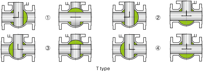
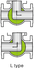
Three way ball valve is effortless to operate and easy to maintain. Five types of flow to meet different process requirements, can be manual, pneumatic, electric control.
Product information

Manufacturing specifications
1. Design: API 6D, ASME B16.34, DIN 3357-1, EN 12516-1, EN 17292
2. End Connection: ASME B16.5, ASME B16.47, DIN2542-2545, EN 1092, GOST 33259
3. Structure length: API 6D, ASME B16.10, DIN 3202, GOST 3706
4. Test and inspect: API 6D, API 598, DIN 3230/3, EN 12266, GOST 9544
5. Applied medium: Natural gas, liquefied petroleum gas
6. Applied temperature: -28℃~150℃
7. Operation: Worm gear, pneumatic, Electric, Pneumatic-hydraulic
Structure Features and usage
Three way ball valve is made up of one worm gear, manual operating stem, and double three-way ball valves.
The feature is that the two ball valves are set symmetrically, with one common stem, reliably and efficiently solving synchronous switching for two symmetrical ball valves. Such valve is easy to operate, and works reliably.
| NO | Part Name | NO | Part Name | NO | Part Name |
|---|---|---|---|---|---|
| 1 | bonnet | 8 | body | 15 | gaskets |
| 2 | nut | 9 | Seal 3 | 16 | packing |
| 3 | bolt | 10 | Seal 4 | 17 | bolts |
| 4 | gaskets | 11 | seat | 18 | Packing Gland |
| 5 | Seal 1 | 12 | O-ring | 19 | limit switch |
| 6 | sphere | 13 | plug | 20 | ring |
| 7 | Seal 2 | 14 | stem | 21 | handle |
Designing Features of Three Way Ball Valve
① Threee way ball valve seat can be designed as four-sided seat floating ball and fixed ball, stable flow, reliable sealing.
② structure can be designed as side-mounted and top-mounted, two-way sealing design, flow direction switching without cascade.
③ Anti-flying stem design.
④ Anti-static design
⑤ Two-position (open and close position) locking design.


Main component materials

| Part Name | Materials | ||
|---|---|---|---|
| Carbon steel | Stainless steel | Low-temperature steel | |
| Bonnet | A216 WCB | A351 CF8M | A352 LCB |
| Nut | A194 2H | A194 8 | A194 4 |
| Stud | A193 B7 | A193 B8 | A320 L7 |
| Gasket | PTFE/Flexible graphite+SS/RPTFE | ||
| Seal ring | PTFE/RPTFE | ||
| Sphere | A105+ENP | A182 F316/F304 | A350 LF3/LF3+ENP |
| Body | A216 WCB | A351 CF8M | A352 LCB |
| Seat | A105+ENP | A182 F316 | A350 LF3 |
| O-ring | 氟橡胶 | ||
| Plug | A105++ENP | A182 F316 | A350 LF3 |
| Stem | A182 F6a | A182 F316 | A182 F316 |
| Packing | PTFE/Flexible graphite | ||
| Bolts | A193 B7 | A193 B8 | A320 L7 |
| Packing Gland | A216 WCB | A351 CF8M | A352 LCB |
| limit switch | A105+ENP | ||
| Ring | 65Mn | ||
| Handle | Q235A | ||
scope of supply
| Nominal diameter | pressure rating | ||
|---|---|---|---|
| DN | In | 150 | 300 |
| 15 | 1/2 | ◉ | ◉ |
| 20 | 3/4 | ◉ | ◉ |
| 25 | 1 | ◉ | ◉ |
| 32 | 11/4 | ||
| 40 | 11/2 | ||
| 50 | 2 | ◉ | ◉ |
| 65 | 21/2 | ◉ | ◉ |
| 80 | 3 | ◉ | ◉ |
| 100 | 4 | ◉ | ◉ |
| 125 | 5 | ◉ | ◉ |
| 150 | 6 | ★ | ★ |
| 200 | 8 | ||
| 250 | 10 | ★ | ★ |
Note: ◉: Handle operated valve ★: Gearbox operated valve
